This pendulum is an 'anti-steampunk' clock. Rather than a modern object with Victorian aesthetic, it's a Victorian object with a modern aesthetic.
[I need to come up with a name for this clock]
This project was (like many of my projects) stuck at 90% done for the last 5 years. Luckily, my new friend Claude has helped me to get it up and running, dealing with many of the challenges I ran up against. I'll be updating this with new information, software, etc.. hopefully soon (Nov 2026)
Until the 20th Century, the most accurate clocks known to science were pendulum clocks. The history goes back to Galileo - who timed the swinging of a lamp in the Pisa cathedral with his own pulse - through Huygens, Foucault, John Harrison, and many others.
Much of the history of the development of the pendulum clock revolved around trying to drive it with the least amount of interference via an 'escapement'. Compensating for errors caused by temperature and pressure variations also presented many difficulties.
The most accurate pendulum clocks of the 20th century were the Schortt-Synchronome clocks, which used a master/slave system with one pendulum inside an evacuated, temperature-controlled chamber. These were accurate to one second within a year.
250 years ago John Harrison (of Longitude fame) designed a clock and made what were considered ridiculous claims about its accuracy. Martin Burgess built a replica, called "Clock B", which was tested in 2014 to one second in a hundred days.
For comparison, your average quartz clock is accurate to about +/- 20 seconds in a month.
Aside from its use as a timekeeper, the pendulum is more properly viewed as a device for measuring local gravity. Extremely accurate pendulum clocks will uncover periodic errors showing up in the data, eventually traced to several cyclical changes in gravity caused by the tides.
Pendulums are still used today in experiments like the Laser Interferometer Gravitational-Wave Observatory (LIGO), which uses a "360kg quadruple pendulum".
[See also https://doi.org/10.1103/PhysRevLett.85.2442]
There's not much point to owning an accurate pendulum clock today. A GPS receiver puts atomic clock accuracy into anyone's hands for $20 or so, and in fact our phones already have those receivers built into them. These are often accurate down to the 50 millisecond range.
Most people have sloppy quartz clocks scattered around their homes, but for accurate time we all rely on our phones and computers, most of which are powered by a combination of NTP (the Network Time Protocol) and GPS.
For myself, I find mechanical clocks fascinating, and their aura of history and engineering triumph are worth appreciating. Large and relatively accurate pendulum clocks are still manufactured today, but are somehwat expensive - a luxury item, for sure.
While reading and thinking about the history of the engineering challenges met over the centuries, I realized that many of the difficult problems of the past could be conquered easily with inexpensive modern electronics & microcontrollers, and I am intrigued by the idea of making an accurate pendulum clock by 'cheating' - rather than compensating for error due to barometric pressure by attaching a series of aneroid capsules and carefully calibrated weights, I can simply measure and calibrate the error and remove it with a line or two of code. Similarly, I can calibrate the effects of temperature on the system and compensate for them automatically. No need for a gridiron pendulum, or bimetallic strips, etc..
It's also much easier today to monitor the performance of the clock, and hopefully this makes the task of compensation & calibration quick and painless.
Pendulums are used for time-keeping because the time it takes for a pendulum to swing back and forth is relatively constant (see 'isochronism'). There are some caveats - the angle of swing needs to be small, most of the weight needs to be near the bottom, the rod should have a constant-ish length, etc.
Mechanical clocks usually arrange for the period to be some nice round fraction of a second, because the clock mechanism itself is driven by that period. Calibrating a pendulum clock usually means trying to get the period as close to its designed value as possible, and keeping it there, usually by means of a small adjustment knob underneath the bob.
  A clock like the one in the "Big Ben" tower has a small tray for
  weights, the operators add or remove coin-sized weights to the
  tray to adjust it while it's running.
Our digital clock doesn't need the period to have a specific value, just that whatever that value is, we know it with great precision, and are able to keep it as constant as possible.
The ideal pendulum is called a "free pendulum" - one that has no interaction with the world around it. If it were possible to build a completely frictionless pendulum (say, in a vacuum, with some kind of zero-friction suspension), and there was no mechanism attached (like an escapement), it would tick perfectly forever.
We can't remove the suspension, and we don't want to put our pendulum in a vacuum chamber - it's less visually pleasing that way - but we can still do a good job by getting rid of the escapement entirely.
In order to power the pendulum we attach a small, powerful magnet to the base of the pendulum, and give it a tiny push with an electromagnetic coil placed under the center of its swing. The position of the pendulum is detected with a Hall Sensor, and by carefully timing the passage of the bob we can send the impulse at "Bottom Dead Center" (BDC), when the impulse will give the greatest push and least distortion to the swing.
We adjust the length of the impulse to be as small as necessary to keep the amplitude of the swing close to our target value. Once settled down, my clock sends a 3ms impulse about 3 out of every 4 swings.
In the horological world, "circular error" refers to the departure from isochronism caused by variation in amplitude. Yes, it's a confusing name. It doesn't have anything to do with pendulum swinging outside a straight-line path. Normally this error would be difficult to measure, because it's small, but using the TCXO we can easily see that the period varies with the amplitude quite noticeably. In fact, I think that much of the error introduced by temperature and pressure changes is actually caused by changes in the amplitude of the swing.
If we control the amplitude of the swing, the period becomes much more stable. For my one-meter pendulum, an increase in amplitude from about 9cm to 12cm causes an increase in period of about 1/1000s. This would correspond to about 90 seconds of error in a day.
Once the amplitude is controlled, the period has a range of about 2/100,000s.
[it ranges between about 2.09936 and 2.09934 seconds.]
When I first started this project, I used the microcontroller's clock to make measurements of the pendulum's swing. It didn't take long to realize that the ESP8266's internal crystal clock is wildly variable, especially vulnerable to environmental temperature changes. Trying to measure time with a ruler that stretches and shrinks depending on the temperature is a fool's errand. So I've added... wait for it... an "extremeley accurate real-time-clock" to the system. It uses a temperature-compensated quartz crystal oscillator (TCXO) to provide a precise timing signal with an error of about 2ppm. It costs about $15.
[three times the cost of the microcontroller itself!]
It is this RTC that has allowed me to measure the period with such accuracy.
Viewed from a certain angle, and with a bit of a squint, one could see the TCXO as a slave clock, since its sole purpose is to precisely time the impulses delivered to the main clock.
If we're assuming a "simple pendulum" (small angle, etc), the period of the pendulum depends only on the length. But don't pull out your tape measure yet. It actually depends on the length from the pivot to the center of gravity (or "center of oscillation"). Since the rod itself has weight, this raises the center of gravity up from the center of the bob by some amount. The easiest way to measure it is to measure the period of your pendulum, and then plug that value into the formula for a simple pendulum:
The length of my pendulum from pivot to center-of-bob is 110cm, which gives a calculated period of 2.105s. But the actual period is 2.0993, giving a length of 109.4cm. Closer than expected! The carbon fiber rod is 1m in length and weighs about 100g. The bob is ~2kg bismuth.
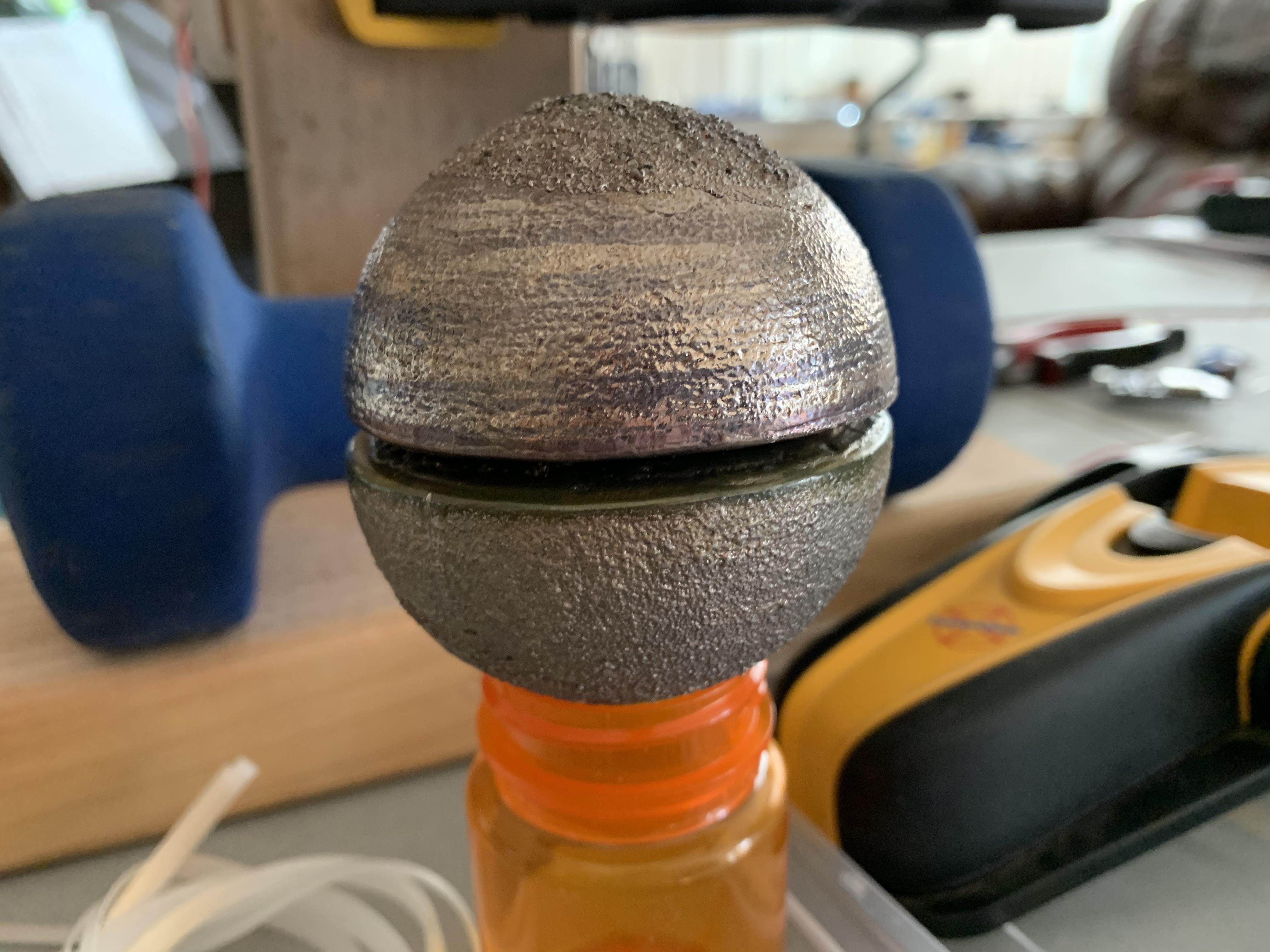
Ideally, we want a dense, spherical bob. A sphere is an improvement over the 'classic disc' shape because it's the most aerodynamic shape when drag in both directions is taken into account. It's also the smallest volume for a given mass. I chose to use bismuth (density 9.8g/cc), which is nearly as dense as lead (11.29g/cc) and much less toxic. If money were no object, I would probably choose tungsten (19.3g/cc). The ~2kg of bismuth in my tennis-ball-sized sphere cost about $80. A ~2kg sphere of tungsten is about $650, and can't really be machined.
My bismuth sphere was cast in two hemispherical pieces, with a bolt embedded in the center of one of the flat faces. A hole was drilled through the other side so that the attachment point of the bob was as near the center of gravity as possible. This compensates somewhat for the thermal expansion of the bob itself.
The rod is a 1m carbon fiber rod, 12mm OD 8mm ID:
https://www.amazon.com/gp/product/B07KWFNM2X/
Only after I started building with the Carbon Fiber did I realize that the ultimate material - fuzed quartz - is available:
https://amzn.com/B00OZXQ0WA
I can't recommend it yet, because I'm not sure how to handle attachment, but my next clock will probably use one of these.
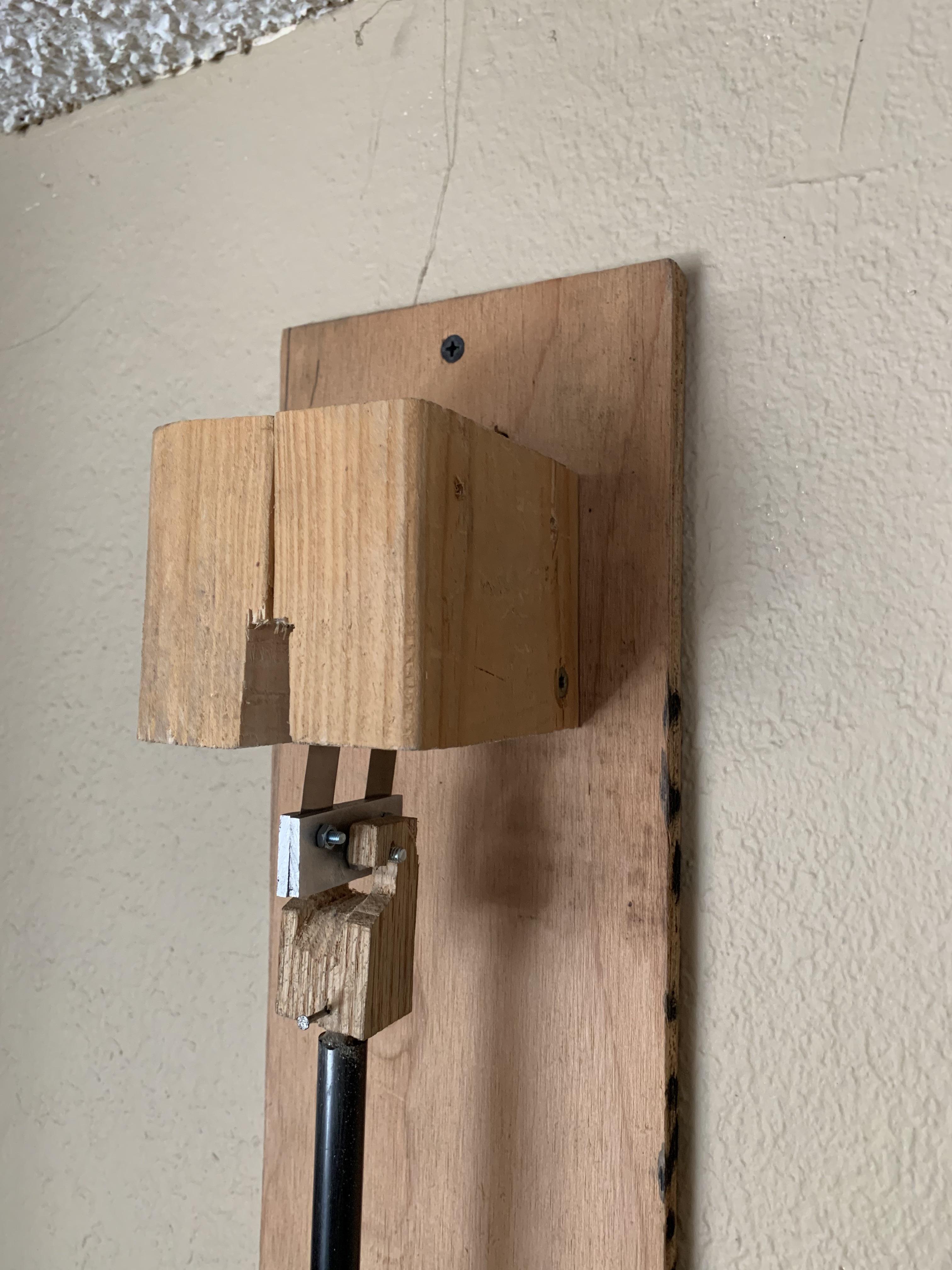
The suspension is made from two 1cm strips of 0.04" spring steel, sandwiched between two 1mm thick aluminum sheets. The strips were taken from a $5 set of feeler gauges from Harbor Freight. There are probably better sources, let me know if you find one.
A hand-carved wooden hook sits atop two side screws of this assembly, which is joined to the rod with a 1/4" dowel. The dowel and pendulum bob are attached to the CF rod with epoxy. I would prefer if the hook assembly were made out of brass, but I don't have access to a machine shop.
Glued to the bottom of the bob (I think with superglue) is a 1cm diameter neodymium magnet, about 2mm thick, similar to these:
https://amzn.com/B07CVPC3YJ/
Aside from the fuzed-quartz rod idea, I was initially trying to come up with a non-spring suspension. I feel like using springy metal there is a bit of a cheat... but I have to admit it works well. It's the standard for a reason.
I tried using a magnetic suspension for a while (using a setup similar to a prop balancer), but I don't think it's possible to get micron-consistent pendulum length this way.
Another idea would be to make some kind of knife-edge suspension, or perhaps using some manufactured sapphires on a hard substrate.
Q Factor[no, not _that_ Q]
An important measure of the pendulum's quality is called 'Q factor', which roughly translates to its ability to swing on freely for a long time. Think of a tuning fork: once you strike it, how long does it continue to ring?
We are shooting for a Q of 10,000+. The main way to increase Q is to reduce resistance/friction/drag/etc. With a quality suspension, a long rod, and a heavy bob, the main input to Q is air resistance. For this reason we want to keep the amplitude of the swing small - because drag is proportional to the square of velocity, and velocity goes up with increasing amplitude. [the pendulum covers a wider arc in the same time period].
[I have a version of the pendulum code that emits telemetry for the pendulum with no impulses, combined with a python script to calculate Q from that. It's tricky because it's not easy to calculate the amplitude directly from the hall sensor data].
The coil is formed from several hundred turns of 28 AWG magnet wire. It's about 4cm diameter, 1.5cm height, with a 1cm hole in the center. It was formed using a 1/4" dowel and a cordless drill.
[pictures here]
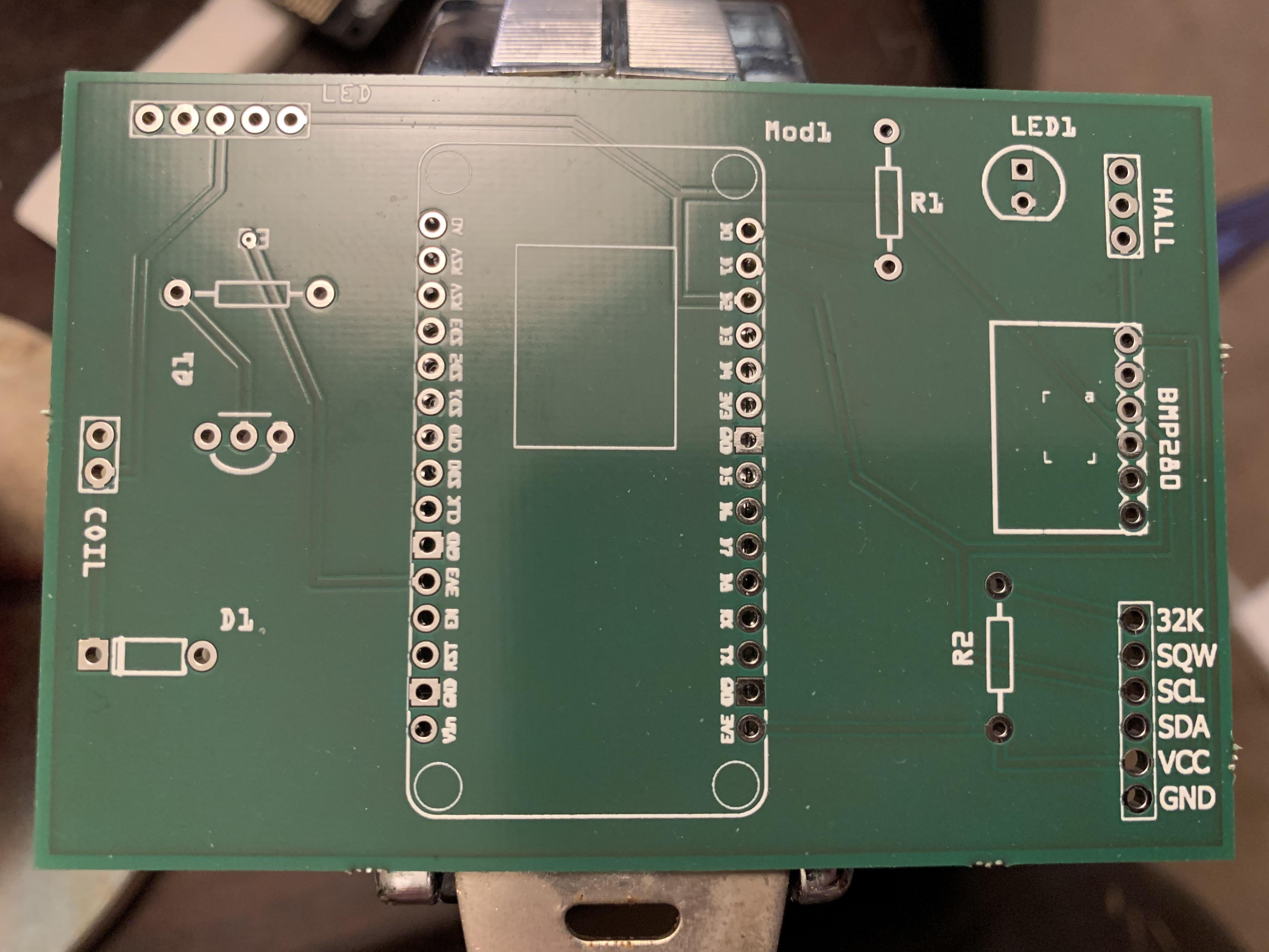
The microcontoller is an ESP8266/NodeMCU, which is an inexpensive ($5) and very popular WiFi-capable board programmable with the Arduino system. Connected to the ESP8266 are a simple transistor control circuit that uses the 5V line (available via USB power) to send a pulse under the control of a GPIO pin.
The real-time clock is a DS3231SN breakout board ($11):
https://amzn.com/B07WWXW5D5
Note: there are many very similar boards available on amazon, and they are often much cheaper. But when I ordered them I received boards with the DS3231M (note the 'M'), which is a MEMS version of the chip that is less accurate, not temperature-compensated, and missing some features.
The temperature and pressure sensor is the BMP280 ($14 for 5)
https://amzn.com/B07RT5J529
The LED display is from Adafruit, using their max7219 backpack ($18):
https://www.adafruit.com/product/1270
Hall effect sensor:
https://www.adafruit.com/product/158
or
https:///amzn.com/B00SWK15ZE
Be careful to buy a switch/sensor, not a latching sensor, and not an analog sensor.
[cover the rest of the BOM here, the transitor, diode, resistors, LED, headers (male & female).] [cover the board design here]
put it up on github. strip out the junk. rename some files.
The clock communicates over the network with UDP.
You'll need to edit arduino_secrets.h to hold your SSID and password. You'll also
want to set the IP address of your telemetry machine.
This receives telemetry data from the clock. I'm using it to collect long-term period/temperature/pressure data in the hopes of eventually compensating them.
This is used to send commands to the clock. Currently, it can adjust the pulse parameters, set the time, adjust display brightness, etc.
[this could turn into an iOS/Android app someday.]
Note: you'll need to change the IP address at the top of the script to match the ipv4 address of your clock. [this is printed to the serial console, which you can see while connected to the Arduino app].
This is a great site for the time-obsessed:
https://leapsecond.com/
This is a very long thread about a doomed and radical pendulum project:
https://www.model-engineer.co.uk/forums/postings.asp?th=167568
It's a fascinating thread though, because a lot of wise nerds chime in on various aspects of the problem. Until I saw this thread, I thought I was alone in my desire to build a 'modernized' pendulum clock. Now I know there are probably hundreds of us.
"My Own Right Time - an exploration of clockwork design" - Phillip Woodward:
https://www.amazon.com/Own-Right-Time-Exploration-Clockwork/dp/0198565224
This is a great - if expensive - book that covers the author's development of a series of pendulum clocks.
You can read about his free pendulum clock here:
http://www.davidwalter.com/dw5-free-pendulum-clock/